|
Theory | |
Exercises | |
|
Lection 3: Resistors
In this lecture, the electric resistance is introduced.
Goal: The goal of this lecture is to have a basic understanding what a resistance is. To know the symbols used in electric circuits to represent resistances and to be able to calculate the total resistance, given a set of parallel and serial resistances.
|
So far, we know about the electric current and about voltage. The last basic element we need for our basic-circuit to work are loads. Loads are electric devices, that consume energy. So all the current and voltage that is produced by the sources is consumed by the loads. The most simple load is a simple resistor. And this is what we will begin with. In the last chapter, you have already seen some resistors in the picture. A resistor is nothing more than a simple resistance to the flowing electric current. A simple example of a well known resistor are the first light bulbs. The first light bulbs were nothing more than just a regular wire going into the light bulb, then a really really thin wire in the glass bulb and then a wire going out of the light bulb again. So when the current flows into to light bulb it first passes the regular wire. This is totally normal for the current, it wont even note a difference. But then it passes through the very thin wire. And because the amount of current does not just simply become smaller, it all has to really press through the wire. Because there is not enough space for all the current if it flows at the same speed, it has to flow faster to get thorugh this really thin wire. This uses more energy. This energy that is released makes the really thin wire hot so that it starts to glow. This is how the first light bulbs worked. |
|||
|
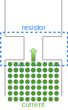
You can compare this to a very large group of people, who are walking down a street. To the left and to the right are houses, so the people can not leave the street.
Now every person represents a single electron. And all of the people walking down the street at a certain velocity are the electric current.
Now say that the people can not just become slower or faster, they should all walk at a fixed velocity.
But at one part of the street, the houses to the left and to the right are standing closer together.
At this position, the street is only half as wide as the rest of the street. This is our resistor. Now the people are at a fixed speed. But when they come across this narrow passage, they can not slow down. So what do they have to do, to all fit though this narrow passage? They have to walk faster! Only if they walk faster, they can all pass though this narrow passage at the same time as if they were passing a regular part of the street. But if they walk faster, they use more energy. This energy is released into the air, and one could say it will become a bit warmer. This is the energy that makes the wire hot and glowing and therefore the light-bulb shining. A light-bulb is one type of resistors, there are many more. For now, we will not care, what type of resistors we have. We just use the standard one. |
||
|
A resistor is a resistance to the flowing electric charge. This resistance is able to take the energy out of the flowing electric charge and use it to light a lamp, to power a computer or many other things.
In the last chapter, we said that voltage is the energy of the electric charge that is flowing through the circuit.
At every resistance, a bit of this energy is lost to allow the current to pass the resistor. |
|||
|
To display a resistor in an electric circuit, we use the symbol that is displayed on the left. As with voltage and current, the resistors have their own unit to measure the strength of the resistor. The unit is called Ohm. One Ohm means that we have one Volt per Ampere. The unit was named after Georg Simon Ohm, a German Scientist who formulated Ohm's law. You will lrean more about Ohm's law in the next chapter. For now, it is only important to know that the unit is called ohm. Sometimes the uppercase greek lettre omega is used, when ohm is meant. So instead of writingL RA= 5 Ohm we can write RA= 5Ω Resistors can be combined in different ways. In parallel, in serial or even both. So lets have a look at the rules. Now for the resistors, there is not a name to the rules of calculation. Nevertheless, it is important to follow this rules! |
||
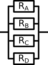
Series ResistorsIf multiple resistors are connected in series, then they can be replaced by one single big resistor. The value of this resistor is just the sum of all smaller resistors.
To replace these four resistors with one large resistor, it is neccesary to calculate the value of the large resistor. The formula is: R = R1 + R2 + R3 + R4 To if we know the values of the small resistors, we can calculate the value of the big resistor. R1 = 3.0Ω R2 = 5.0Ω R3 = 1.5Ω R4 = 4.5Ω So the calculation is: R = R1 + R2 + R3 + R4 R = 3.0Ω + 5.0Ω + 1.5Ω + 4.5Ω = 14.0Ω Now you have seen how to add up resistors that are connected in series. If you replace multiple resistors with one larger one, we call this the replacement resistor. Parallel ResistorsIf multiple resistors are connected in parallel, they can be replaced by one single big resistor, a replacement resistor. But the calculation of the replacement resistor is more complicated than for the series resistors. It is very important that you follow this rule. If you have trouble with the calculation, use a calculator!The replacement resistor of parallel resistors is the inverse of the sum of the inverse values of the resistors. Now this might sound complicated so let's have a look at an example: |
|||
|
The formula to calculate the replacement resistor is: 1⁄R = 1⁄R1 + 1⁄R2 + 1⁄R3 + 1⁄R4 Again we are given the same values as in the last example. R1 = 3.0Ω R2 = 5.0Ω R3 = 1.5Ω R4 = 4.5Ω So the equation for the replacement resistor is: 1⁄R = 1⁄3.0 Ω + 1⁄5.0Ω + 1⁄1.5Ω + 1⁄4.5Ω The calculation can be done using a calculator on the computer, if you you are not sure how to do the math exactly. It would go beyond the scope of this course to go into details about mathematical calculations and refomrulations. The last part of the equation needs to be reformulated: 1⁄R = 0.8888⁄Ω R = 1.125Ω Surprisongly, the replacement resistor is smaller than to original resistors. Why is that so? The answer is that if you link the resistors in parallel, the current has more different ways to pass and therefore less resistance than more. So the resulting resistor is smaller. |
|
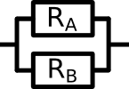
Let's have a look at a smaller example. Two resistors are linked in parallel. Both have a resistance of 1 Ω. So the current which is passing through this passage suddenly has two different ways to flow, instead of just one.
Both ways have the same resistance, but because halfe of the current can go one way and the other half the other way, the current is acctually facing less resistance. The calculation would be: 1⁄R = 1⁄R1 + 1⁄R2 1⁄R = 1⁄1 Ω + 1⁄1 Ω = 2⁄1 Ω R = 1⁄2 Ω |
So now you know a bit about resistances and how to add them up in an electric circuit.Conclusion and short repetitionLet's briefly list all the important information of this chapter in a short list.
Now go to the exercises, to train your knowledge. The first part of the exercises are about adding resistors up in series. THe second part is about resistors in parallel. Before you go to the third quiz, have a look at chapter 3.1 where a brief example is given of how to handle many resistors which are linked in parallel and series. |
|||