|
Theory | |
Exercises | |
|
Lection 2: Voltage
In this lecture, voltage is introduced.
Goal: The goal of this lecture is to have a basic understanding what voltage is. To know the symbols used in electric circuits to represent voltage and voltage sources and to be able to calculate voltage. This includes Kirchhoff's voltage law.
|
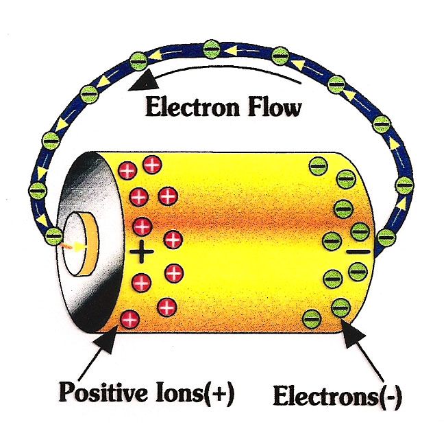
In the last chapter, the electric current was introduced. But it was never explained as to why the electrons that make up the current are moving.
If we want to move something, we always need a force to make a movement. The same holds for the electric current. The electrons do not just move because they are bored and want to go for a stroll. As mentioned before, electrons have a negative charge. And with this charge, they are attracted to any positive charge, that they see. Usually, this positive charge is given by positive ions. Atoms that have more protons than electrons and therefore are positively charged. |
|||||
|
In a battery, some electrons are sepparated from their atoms.
This leavs a mass of electrons who are looking for positively charged ions on one side, and a mass of positive ions on the other side.
This process is done chemically. When we use a battery, we connect the negative and the positive part and the current is able to flow until there are no more electrons left on the negative side and no positive ions on the positive side. Then a battery is empty. If it is a rechargeable battery, it is possible to sepparate the electrons and atoms again by connecting the battery to an electric circuits. This is the recharging of the battery. |
||||
|
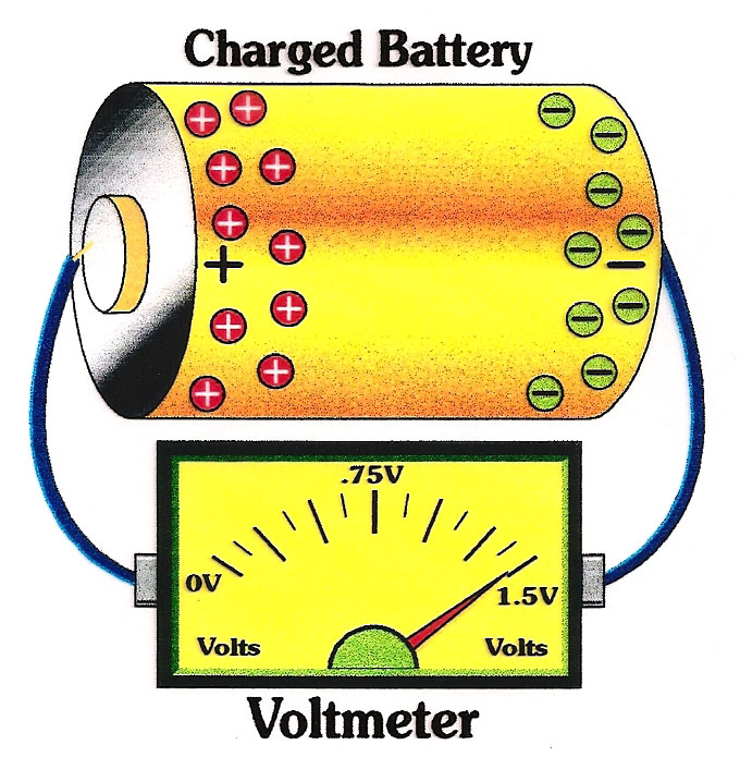
Now what about the voltage? Voltage is the energy with which every electron flows towards to positive charge. We use a unit to quantify about this energy, the Volt. This was named after Alessandro Volta, an italian physicist who invented the first battery in the 1800s. |
|||||
|
Alessandro Volta invented not only the first battery, but also a volt meter.
A device to measure the energy of the electrons, which are flowing though a wire. The voltage depends on the difference between the charges. If on one side, there are 1000 positive ions, the electrons on the other side are more attracted to them than if there were only 100 positive ions. More attraction means more energy and a higher voltage. But if there are only 100 positive ions, the electrons are less attracted to them. One might think, that a higher current, i.e. more Ampere, leads to higher voltage. But this is wrong. The current can be very high, but the voltage low and the other way around. Imagine, the current as a river. Every drop of water is an electron. The current describes how many water drops per second pass through the river. The voltage describes what energy this waterdrops have. This means, the voltage describes the kinetic energy of the water. Now there are rivers, with a lot of water in them. But they move very slowly, the stream is not very strong. Think about the river delta next to Douala. The river there is very large, but moves slowly and is not powerfull. On the other side, then there are small rivers where the water moves very fast, with a lot of energy. A good example for these are rivers that are up in the mountains. Small mountain rivers ofthen have a lot of energy because they are moving down the hill. So you see, large current, does not necessarily mean large voltage. These two properties are not directly linked to each other. |
||||
How are voltage sources used in electric circuits, and how to we calculate with them? |
|||||
|
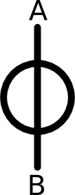
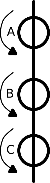
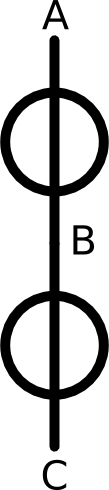
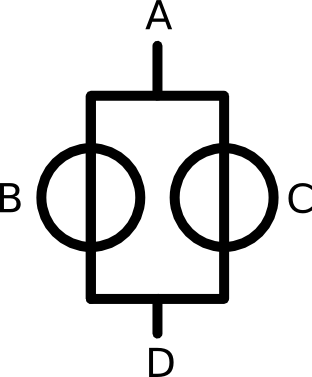
Voltage sources look very similar to current sources. Their sign is also a circle with a line.
But the line is vertical, not horizontal as with the current source. As mentioned before, if we need to calculate the voltage in a circuit, we use the unit Volt. Now the cee an example of how to calculate the voltage, see the second picture on the left. Here, we see three different voltage sources, A B and C. The little arrow to the left of each source show into which direction the voltage should go. This is similar to the little arrow we used for the current. It might be that we draw the arrow in the wrong direction, so it is possible that the voltage can be negative. Now the question could be, what is the total voltage on this picture on the left? We know that votlage source A has 50 Volt, voltage source B has 35 Volt and voltage source C has 45 Volt. The total voltage over all of the three sources is therefore A + B + C = 50V + 35V + 45V = 130V. If you want or need to connect voltage sources, be careful. Only connect the voltage sources in serial, unless you know exactly what you are doing and have a very good reason for it. |
||||
|
|
||||
As with the current, there is also a Kirchhoff's Law for voltage.
It describes exactly how to add up the voltage and it is essetial to know this law and understand it.
If we follow this law, it is not too difficult to calculate all kinds of electric networks. Kirchhoff's Voltage lawThe second Kirchhoff law is sometimes also called the Korchhoff's loop or mesh rule.The essence of this second rule is that in a loop within a network, the total amount of voltage always has to sum up to zero. This sounds very much like Kirchhoff's first law with the conservation of current, right? But what does this second rule mean? |
|
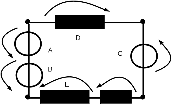
Every electric circuit consists of different loops. Within each loop, all the voltage has to sum up to zero.
The arrows indicate in which direction the voltage is going. Probably the best way to approach this rule is to look at the loop in a counter clockwise direction. Sum up all voltages of the arrows, who are pointing counter clockwise. Then subtract all voltages of the arrows pointing in a clockwise direction. An explanation for this second Kirchhoff's law is that all voltage that is produced in a loop has to be consumed somewhere in the same loop. Let's have a look at the example on the left. You can see the example of a simple electric circuit with just one loop. Now Kirchhoff's Law states, that the sum over all voltages has to be zero. This means, we can add up all voltages according to their direction. In the case of the example to the left, this equation would be UA + UB + UC - UD - UE - UF = 0. Note that if we speak about the voltage at a point X we will refer to it as UX. We have used I to refer to current and we will use U to refer to voltage. The voltage that is produced by the sources A, B and C has to be consumed by the resistors D, E and F. The voltage can not just vanish into thin air. |
|||
|
We know the following data: Voltage source UA: 30 V Voltage source UB: 25 V Voltage source UC: 10 V Resistor UD: 40 V Resistor UE: 5 V How much voltage is used by resistor F? First we sum up all voltages counter clockwise. The arrows over A, B and C point counter clockwise. So we add up UA + UB + UC = 30V + 25V + 10V = 65V. Then we subtract all clockwise voltages from this value. The arrows D and E are clockwise. F is also counter clockwise, but we do not know the value of F. That is what we try to calculate now. So the calculation is 65V - UD - UE - UF = 0. But since we do not know the voltage of F, we reformulate this equation to 65V - UD - UE = UF. Now filling in the numbers: 65V - 40V - 5V = UF = 20V. Direction of arrowsIn the last chapter, we already saw that the direction of the arrows is very important for the current. Sometimes the current can even be negative.Now with the voltage, the situation is a little bit different. Voltages can never be negative as long as we are working with direct current! So if you are drawing your own electric circuit, you have to be very careful with the direction of the arrows aver the voltage sources, resistors and other elements. What is the rule when you draw the direction of the arrows?
So now you know a bit about voltage and how to calculate with it in an electric circuit. Conclusion and short repetitionLet's briefly list all the important information of this chapter in a short list.
Now go to the exercises, to train your knowledge. The exercises are all about the second Kirchhoff's law that you have just learned. |
|||||